
In 1782, James Watt built the first double-sided
low pressure steam engine with rotating motion.

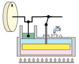
The animation of the figure above shows the engine's mode of operation. The valve above and the piston below are connected to the crankshaft via a connecting rod. Both oscillating cylindrical parts seal closely with the surrounding cylinder. The ratio of net power obtained divided by the heat input is the efficiency. In this low pressure steam engine, the efficiency is only 3%.
The Stirling engine opens up the possibility of using heat from diverse sources, such as sunlight
or fuel combustion. However, it has a less than favorable power to weight ratio.
It works without valves with a constant volume of gas,
such as helium. On one side of the cylinder, the gas is heated. On the other side, it is cooled. In between,
a voluminous piston (yellow) moves as a heat accumulator, which removes heat from the quickly flowing gas as
it flows from the hot side to the cold side and then adds the heat back when the gas flows in the other
direction. A second piston (green) seals the cylinder up tightly. At the left is a picture of an animation
from the Stirling engine website of
K. Hirata;
see also Robert Sier's website.
Robert Stirling patented the first hot gas motor in 1816 and built one in 1818. At the end of the 19th century, the Stirling motor was widely used for small machines. Even now, at the beginning of the 21st century, this has not been forgotten.
The efficiency of the Carnot process, η = (Th − Tc) / Th , represents the upper limit on the efficiency of any steam engine. From the equation, one can see that using the hottest possible steam leads to higher efficiency. The cooling temperature of 300 K (27 °C or 81 °F) cannot easily be changed. Watt’s low pressure steam engine works with a temperature below 400 K and a pressure of about 0.3 bar above atmospheric. This cycle is not equivalent to the Carnot cycle, and therefore has a lower efficiency. The rather low efficiency of 3% is also due to friction within the machine, which reduces the amount of usable mechanical energy obtained. Subsequent high pressure steam engines for railways used temperatures up to 350 °C and higher pressures. In rare cases, this has resulted in boiler explosions. In the UK, there were 122 such explosions in the 19th century dropping to 15 in the 20th century. As recently as 2001 an antique Case-ploughing engine exploded in Medina, Ohio.
These historical models have been replaced with gas and steam turbines for modern applications in power plants operated with fossil and renewable fuels, nuclear power, or solar thermal energy. The upper temperature limit for these has reached 585 °C in 2021 due to improvements in the material properties of the turbines. This change is expected to increase the efficiency of the turbines from 40% to 50%.
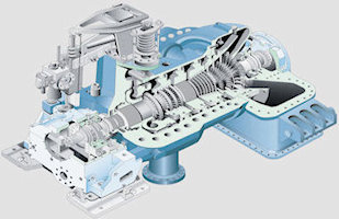
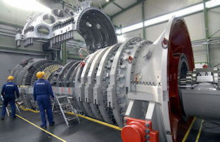
The pictures below (Siemens press pictures) give an idea of the structure and size of turbines currently in use. To the left is a section of a 150-MW steam turbine and the picture to the right shows the installation of a 340-MW gas turbine. Gas turbines have a compressor and combustion chamber in front of the blades and vanes, which also occur in steam turbines.
Combined cycle power plants generate electrical power by combining gas and steam turbine processes. In gas turbine combined-cycle (GTCC) applications, high-temperature exhaust gas from the gas turbine is used to generate power in a steam turbine. A combined cycle power plant produces electricity with one to three gas turbines and one steam turbine, where either each turbine drives a separate generator or a gas turbine with the (disconnectable) steam turbine act on a common shaft to the generator. The hot exhaust gases from the gas turbines are used in a waste heat boiler to generate steam. The steam is then expanded through a conventional steam turbine process. About 2/3 of the electrical power comes from the gas turbine and 1/3 from the steam process. Currently, combining the two turbine types results in high power efficiencies up to 60%. Other acronyms are CCPP (combined cycle power plant) or CCGT (combined cycle gas turbine).
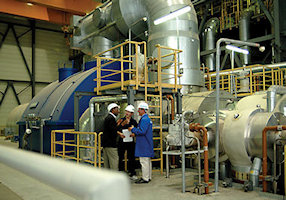
The picture to the left (Siemens press picture) shows the steam turbine of the combined-cycle power plant in Mainz-Wiesbaden, which consists of gas turbines, steam turbines, and air-cooled generators. The plant generates an output of more than 400 MW and allows the extraction of steam (see below). Combined cycle power plants produce mainly medium-load power and peak current because of their quick start-up ability and higher electrical costs when compared to steam-turbine power plants.
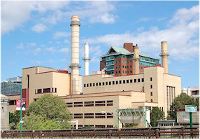
Unlike thermal power plants that are designed only for power production, installations for combined heat and power (CHP) or cogeneration can achieve a higher efficiency of 60% by the simultaneous production of usable heat (for heating buildings or for production processes) and electricity. The performance range currently extends from a few kilowatts for homes up to one gigawatt for large facilities. The picture above to the right shows a 250-MW cogeneration plant in Cambridge, Massachusetts.